Steam Sample Conditioning & Measurements
Sampling for steam & water measurements
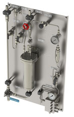
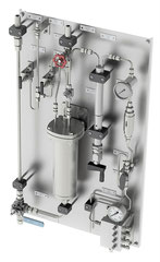
Sample Conditioning Panels are designed for proper conditioning of your steam and water samples. We take care from sample tap to sampling conditioning and analysis.
Built as per standard ASME PTC 19.11 and/or VGB/DGRL.
Mechatest standard sample conditioning panels for steam and water sampling purposes, the objective of water and steam sample conditioning is to modify and control sample temperature, pressure, and flow rate from the sample source to delivery for grab sampling or on-line analysis.
- Control Your Steam Quality
- Increase lifetime of your steam applications
- Prevent corrosion in boilers and pipelines
- Optimize steam chemical composition
- Extract true representative samples of your steam water cycle
- Reliable / stable measurement
- Lower maintenance costs
- Longer lifespan of the equipment
Mechatest standard sample conditioning panels for steam and water sampling purposes, the conditioning systems has the main function to reduce and regulate the temperature, flow and pressure of the sample.
This kind of sampling panels are mostly used in combination with water analyser equipment for analysis on chemical parameters like conductivity, pH, dissolved Oxygen, Silica, Sodium etc.
The systems can be ordered in many versions (low or high pressure, low or high temperature, low or high sample flow) in combination with several options. The panels are designed with best quality products for safe operation and representative sample at the desired pressure and temperature. The systems can be ordered in four versions in combination with several options.
This sampling panel is used in power plants and mostly used in combination with water analyser equipment for analysis on chemical parameters like Conductivity, pH, Dissolved Oxygen, Silica and Sodium. The panels are used for sample conditioning and collection.
- For apllications Demi Water
- Feedwater
- Condensate
- Boiler Water
- LP Drum Water
- LP/HP Steam
- Life Steam
- Main Steam Demi Water
- LP Drum Water
- Steam and Water Analysis System (SWAS), Analysis of pH, Conductivity, Silica, Sodium, Dissolved Oxygen, Phosphate, Chlorides, TOC for power stations
- ASME PTC 19.11-2008 Steam and Water Sampling, Conditioning, and Analysis in the Power Cycle
- ASTM D1066 Standard practice for Sampling Steam
- ASTM D1192 / D3370 Standard Guide for Equipment and Practices for Sampling Water and Steam
- SO 5667.7 Water Quality-Sampling – Part 7: Guidance on sampling of water and steam in boiler plants
Steam Sampling Standards
- ASME PTC 19.11-2008 Steam and Water Sampling, Conditioning, and Analysis in the Power Cycle
- ASTM D1066 Standard practice for Sampling Steam
- ASTM D1192 / D3370 Standard Guide for Equipment and Practices for Sampling Water and Steam
- SO 5667.7 Water Quality-Sampling – Part 7: Guidance on sampling of water and steam in boiler plants
- VGB/DGRL

Steam Sample Panel Selector
| Type | P&T Specifications | Typical Application |
| LPMT |
Low Pressure & Medium Temperature
max. 35 bar @ 232 °C • Single phase max. flow 72 L/h |
• Demi Water • Feedwater • Condensate • Boiler Water |
| LPHT |
Low Pressure & High Temperature
max. 35 bar @ 538 °C • Single phase max. flow 108 L/h • Steam phase max. flow 60 L/h |
• Demi Water
• Feedwater • Condensate • Boiler Water • LP/HP Steam • Life Steam |
| HPMT |
High Pressure & Medium Temperature
max. 345 bar @ 232 °C |
• Demi Water
• Feedwater • Condensate • Boiler Water |
| HPHT |
High Pressure & High Temperature
max. 345 bar @ 538 °C • Single phase max. flow 108 L/h • Steam phase max. flow 60 L/h |
• Demi Water
• Feedwater • Condensate • Boiler Water • LP/HP Steam • Life Steam |
| HPXT |
High Pressure & Extreme High Temperature
max. 345 bar @ 600 °C • Single phase max. flow 108 L/h • Steam phase max. flow 60 L/h |
• HP Steam • Life Steam |
| HPHF |
High Pressure & Extreme Flow
max. 345 bar @ 538 °C • Single phase max. flow 210 L/h • Steam phase max. flow 120 L/h |
• Demi Water • Feedwater • Condensate • Boiler Water • LP/HP Steam • Life Steam |
| HPXF |
High Pressure & Extreme Flow
max. 345 bar @ 538 °C • Single phase max. flow 300 L/h • Steam phase max. flow 120 L/h |
• Demi Water • Feedwater • Condensate • Boiler Water • LP/HP Steam • Life Steam |

Steam Cooling Panel - LPMT
Low Pressure, Low Temperature Steam Sample Panel
• Multi stream (up to 3) analysers
| Sample pressure (recommended) | < 35 bar |
| Sample temperature (recommended) | Max. 250°C |
| Flow single phase samples (Water / Condensate) | Max. 72 L/h |
| Flow condensing samples (Steam) | Not recommended |
| Cooling water flow | Max. 1100 L/h |
| Sample tube length and cooling area | 1/4" OD - Approx. 5.5 m (0.11 m2) |
| Sample cooler (recommended) | Sentry TSR-4225 |

Steam Cooling Panel - LPHT
Low Pressure, High Temperature Steam Sample Panel
• Multi stream (up to 3) analysers
| Sample pressure (recommended) | < 35 bar |
| Sample temperature (recommended) | Max. 538°C |
| Flow single phase samples (Water / Condensate) | Max. 108 L/h |
| Flow condensing samples (Steam) | Max. 60 L/h |
| Cooling water flow | Max. 1500 L/h |
| Sample tube length and cooling area | 1/4" OD - Approx. 11 m (0.22 m2) |
| Sample cooler (recommended) | Sentry TLR-4225 |

Steam Cooling Panel - HPMT
High Pressure, Medium Temperature Steam Sample Panel
• Multi stream (up to 3) analysers
| Sample pressure (recommended) | > 35 bar (max. 345 bar) |
| Sample temperature (recommended) | Max. 250 °C |
| Flow single phase samples (Water / Condensate) | Max. 72 L/h |
| Flow condensing samples (Steam) | Not recommended |
| Cooling water flow | Max. 1100 L/h |
| Sample tube length and cooling area | 1/4" OD - Approx. 5.5 m (0.11 m2) |
| Sample cooler (recommended) | Sentry TSR-4225 |

Steam Cooling Panel - HPHT
High Pressure, High Temperature Steam Sample Panel
• Multi stream (up to 3) analysers
| Sample pressure (recommended) | > 35 bar (max. 345 bar) |
| Sample temperature (recommended) | Max. 538°C |
| Flow single phase samples (Water / Condensate) | Max. 108 L/h |
| Flow condensing samples (Steam) | Max. 60 L/h |
| Cooling water flow | Max. 1500 L/h |
| Sample tube length and cooling area | 1/4" OD - Approx. 11 m (0.22 m2) |
| Sample cooler (recommended) | Sentry TLR-4225 |

Steam Cooling Panel - HPHF
High Pressure, High Flow Steam Sample Panel
• Multi stream (up to 4) analysers
| Sample pressure (recommended) | > 35 bar (max. 345 bar) |
| Sample temperature (recommended) | Max. 538°C |
| Flow single phase samples (Water / Condensate) | Max. 210 L/h |
| Flow condensing samples (Steam) | Max. 120 L/h |
| Cooling water flow | Max. 1500 L/h |
| Sample tube length and cooling area | 3/8" OD - Approx. 11 m (0.33 m2) |
| Sample cooler (recommended) | Sentry FLR-6225 |

Steam Cooling Panel - HPXF
High Pressure, High Flow Steam Sample Panel
• Multi stream (up to 6) analysers
| Sample pressure (recommended) | > 35 bar (max. 345 bar) |
| Sample temperature (recommended) | Max. 538°C |
| Flow single phase samples (Water / Condensate) | Max. 300 L/h |
| Flow condensing samples (Steam) | Max. 120 L/h |
| Cooling water flow | Max. 2700 L/h |
| Sample tube length and cooling area | 3/8" OD - Approx. 15 m (0.44 m2) |
| Sample cooler (recommended) | Sentry FXR-6222 |

Steam Cooling Panel - HPXT
High Pressure, High Temperature Steam Sample Panel (second cooler)
• First and Second Stage Cooling
• Posibility to use two different cooling medium
• Multi stream (up to 3) analysers
| Sample pressure (recommended) | > 35 bar (max. 345 bar) |
| Sample temperature (recommended) | Max. 600°C |
| Flow single phase samples (Water / Condensate) | Max. 108 L/h |
| Flow condensing samples (Steam) | Max. 60 L/h |
| Cooling water flow | Max. 2x 1500 L/h |
| Sample tube length and cooling area | 1/4" OD - Approx. 22 m (0.44 m2) |
| Sample cooler (recommended) | 2x Sentry TLR-4225 |
Steam Sampling Components
Steam Sample Coolers
- Single Helical Tube Sample Cooler
- Design accordingly ASME PTC 19.11 and VGB/DGRL
- Compact, high efficiency sample coolers for cooling high temperature/high pressure liquid or gas samples
- Temperature ratings to 593°C at 345 barg (1100°F at 5000 psig)
- Models available for ultra-supercritical power plants with temperature ratings to 621°C at 356 barg (1150°F at 5175 psig)
- Exotic materials such as titanium, Inconel® and Hastelloy® on the tube side, and Monel®, cupronickel, and stainless steel on the shell side are available
- Highest efficiency sample cooler commercially available
- Various configurations available to meet EPRI/ASTM/ASME sampling guidelines
- Many models are available with ASME section VIII code stamp, CE or CRN registrations
- No dead spots or crevices
- Sample flow rates up to 5.7 liters per minute (1.5 gallons per minute GPM); for higher flow rates see
Steam Pressure Reducing Valve Sentry VREL
- High Pressure Sample Flow Control Valve
- The VREL® is an adjustable sample pressure reducer for sample pressures above 34.5 barg (500 psig) according to ASME PTC 19.11 and the Annual Book of ASTM Designation D3370. A precisely machined tapered rod assembly moves inside precision holes within the barrel of the VREL®. Pressure drop is a function of the length of the rods inserted into the barrel.
Sentry Thermal Shutoff Valve (with reset button)
- Shuts down high temperature sample in less than 5 seconds.
- Need to reset by push button after sample is cooling down
- Protect operators, analyzers and sampling components from high temperature liquids with a Sentry Thermal Shutoff Valve. The sensor/actuator is directly exposed to the sample, providing quick reaction time. Economical and highly reliable replacement for solenoid shutoff valve and temperature controller.
- Suitable for system pressures up to 4400 psi (303 bar)
- Totally mechanical design requires no electricity, air, or hydraulics
- Optional dry contact for remote indication
- Standard trip temperature is 120ºF (49ºC) with other temperatures available
- 316 Stainless Steel construction
Thermal Shutoff Valve (automatic)
- Thermal Shutoff Valve (automatic)
- ThermOmegaTech
- Protects expensive and delicate sample analyzers
- Automatically resets when sample cools
- No outside power required
- Superior value vs. more expensive electric valves
Design Features
- Self-operating thermal actuator controls flow based on fluid temperature
- Operating temperatures unaffected by variable inlet pressures
- Wide choice of setpoints available
- Ram-type plug provides tight shutoff
- Corrosion resistant: all stainless steel construction
Typical Applications
- Excessively hot samples can cause damage to expensive and sensitive hardware and electronics. For process analyzers and similar instrumentation, it is important to assure that the process samples fluids are always below the maximum allowable temperature for such instruments. Sample coolers are commonly used to reduce sample temperatures to the acceptable limits. In the event of a loss of cooling fluid to the sample cooler, or if the desired sample temperature is exceeded for any reason, the HST valve will close to prevent equipment damage. HST valves are covered with our standard 36 month prorated warranty.
Operation
- The HST (High Sample Temperature) safety shutoff valve is used to sense the sample temperature after the sample cooler. The sample passes through this normally open valve whenever the sample temperature is below the valve setpoint. If the sample temperature exceeds the valve setpoint, the HST closes to protect expensive and delicate analyzers and other instruments from overtemperature damage. When the HST cools below the setpoint, it will automatically reset open again.

Refillable Cation Exchange Resin Columns
- Minimize "dead volume" assuring representative samples
- Three models* (RC-100, RC-200 and RC-400) meet your specific requirements, withstanding the demands of power plants
- Column(s) provide optimum fluid velocity with increased resin efficiency
- Color-changing resin gives quick visual indication of resin depletion level
- Twist-off cap for easy resin refill with available pre-sized Sentry resin refill packets
- No PVC; wetted materials will not leach chlorides or plasticizers
Magnetic Trap Filter
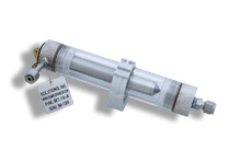
- Magnetic Trap is effective in removing magnetite and other iron particles from samples. It is easy and intuitive to clean and service.
- The magnet inserts into the "dry well" and does not contact the sample fluid. Magnetite sticks on the wetted side of the drywell. To clean the trap simply divert the sample outlet to drain and remove the magcore from the drywell to flush the magnetite and debris from the trap.
- The cleaning process requires no disassembly of the trap or exposure of the sample to atmosphere. This is especially beneficial when it is used to remove iron oxides and other magnetic material from a sample that feeds Dissolved Oxygen analysers or other sensitive instruments.
Technical Details:
- Rating: 13.8 bar @ 24°C
- Max. Temperature: 65°C
- Dead Volume: 30 ml
Location of Steam Sample Tap Point
Samples must be taken from locations that are representative of the water source, steam boiler, treatment plant, points at which water is
delivered to the consumer, and points of use. Design sampling points accordingly ASME PTC 19.11, each locality should be considered individually; however, the following general criteria are
usually applicable:
Sampling points should be selected such that the samples taken are representative of the different sources from which water is obtained by the public or enters the system.
These points should include those that yield samples representative of the conditions at the most unfavourable sources or places in the supply system, particularly points of possible
contamination such as unprotected sources, loops, reservoirs, low-pressure zones, ends of the system, etc.
Sampling points should be uniformly distributed throughout a piped distribution system, taking population distribution into account; the number of sampling points should be proportional to the
number of links or branches.
The points chosen should generally yield samples that are representative of the system as a whole and of its main components.
Sampling points should be located in such a way that water can be sampled from reserve tanks and reservoirs, etc.
In systems with more than one water source, the locations of the sampling points should take account of the number of inhabitants served by each source.
There should be at least one sampling point directly after the clean-water outlet from each treatment plant.
Isokinetic Sampling Probes For Steam Applications
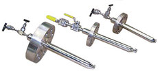
- Isokinetic Sampling Nozzles (Probes)
-
Sampling gases and liquids for on-line and grab sample chemical analysis can be a major source of errors. Up to several orders of magnitude concentration changes of dissolved and suspended impurities have been observed when sample withdrawal, cooling, or transport are not properly performed. Multi-port Steam Sampling Nozzles (Probes) are rarely used because of their complexity, cost, non-isokinetic characteristics, and problems with use in large pipes and they are no longer a part of the ASTM D1066 standard.
A more appropriate and functional design was developed and the design and performance of these nozzles was verified in the Electric Power Research Institute (EPRI) research project RP2712-8. This design was then included in ASTM D1066, "Standard Practice for Sampling Steam". Additional information about the need for isokinetic sampling and the proper design and operation of a sampling system can be found in a technical article entiled "Sampling Savvy"
- ASME PTC 19.11 The specification requires a "isokinetic sample nozzle" for representative sampling of the specific two-phase saturated steam flow via sample ports drilled in the side of the nozzle facing the steam flow.
-
Recommended ONLY for saturated steam in steam boiler and power plants, for superheated steam (only if particulates are
measured), isokinetic sampling is normally not required for water samples.
Click here and see our standard sample probes for non-isokinetic sampling.
- These nozzles meet also the requirements of ASTM Standards D1066 and D3370.
- The nozzles extract a representative isokinetic sample from a flow region removed from the pipe surface and at the average flow velocity of the sample fluid.
- This arrangement results in the withdrawal of the sample with representative concentrations of dissolved, suspended, and volatile constituents. Other applications include oil in water, water in oil, propant in oil, and sand in oil.
- An appropriate nozzle (probe) is designed for the desired sample flow and typical conditions of the sample fluid. When the flow velocity through the pipe changes, sample flow should be adjusted to maintain isokinetic sampling.
- Each Nozzle (probe) is designed with considerations of vortex shedding, resonance, vibration, erosion, and strength of the attachment to the pipe.
The nozzles extract a representative isokinetic sample from a flow region removed from the pipe surface and at the average flow velocity of the sample fluid. This arrangement results in the withdrawal of the sample with representative concentrations of dissolved, suspended, and volatile constituents.
An appropriate nozzle (probe) is designed for the desired sample flow and typical conditions of the sample fluid. When the flow velocity through the pipe changes, sample flow should be adjusted to maintain isokinetic sampling.
For superheated steam applications, it is not recommended to install the Nozzle in locations where the steam temperature is not at least 100F above the saturation temperature.
It is not recommended to install the Nozzle immediately after desuperheaters, in locations where there are large temperature changes, or where there is high carry-over of sodium hydroxide. Where these conditions exist, there should be more frequent inspection of the Nozzle, Nozzle attachment, valves, and welded tubing up to the primary cooler. If installed downstream of desuperheating sprays, the Nozzle location should be far enough downstream where complete mixing has occurred.
The preferred location for the installation of the Nozzle is in long vertical sections of the pipe, away from all flow disturbances (bends, valves, etc.). Ideally, the Nozzle should be at least 35 pipe internal diameters downstream and 4 pipe diameters upstream of any flow disturbances. If this is not possible, place the Nozzle in such a position that the ratio of its distance from the upstream disturbance to the downstream disturbance is about 9:1. If a long vertical section of pipe is not available, the Nozzle may be installed in a long horizontal section in the 10 to 2 o=clock position.
THE NOZZLE OPENING SHOULD FACE UPSTREAM THE SAMPLE PROCESS FLOW.
At the isokinetic sampling rate, the size of the condensed sample line after the cooler should be selected to obtain a minimum flow velocity of 5 to 6 ft/sec (turbulent flow) in the sampling line. This will reduce the possibility of impurity deposition in the sampling line. Typically the required tube size after the primary sample cooler is ¼ inch OD, 0.049 inch wall thickness 316 SS tube.
There should be at least 6 hours of isokinetic sample flow to stabilize the sampling system before taking a sample for analysis. Continuous flow is preferred.
Source reference: Jonas, Inc.

Be part of the best solution, it all starts with you!
We make sampling solutions helping to protect the environment now and for future generations, together we can make a difference.
| Doedijns - Mechatest Sampling Solutions | Vydraulics Group | Vremac | Sypack | |
| Bleiswijkseweg 51 | Telephone & Email | Hydropack | Koppen & Lethem | |
| 2712 PB Zoetermeer | +31(0)88 091 2811 | Vapo | GDM | |
| The Netherlands | sales.mechatest@vydraulics.com |


